Breng je idee tot leven samen met een robot
Heb je al ooit een voorwerp in gedachten gehad dat je graag zou willen maken, maar je weet niet hoe je eraan moet beginnen? Of krijg je nu een idee? Mijn systeem helpt je om het werkelijkheid te maken.
Het systeem is speciaal ontworpen om onervaren gebruikers te ondersteunen. Met behulp van de design tool ontwerp je jouw idee. Daarna bouw je dit model samen met de robot, waarbij deze fungeert als derde hand.
THE BEST OF BOTH WORLDS
Er bestaan veel vooroordelen wanneer het gaat over robots. Zo zouden ze jobs kunnen afnemen van mensen, of veroveren ze zelfs de wereld in sommige films.
Gelukkig is dit niet hoe men in onderzoek of in de industrie naar robots kijkt. Hier wordt er gezocht naar manieren waarop mensen en robots kunnen samenwerken, om zo het beste uit elkaar te halen. Ze hebben namelijk beiden unieke eigenschappen die elkaar ondersteunen. Een robot kan continu geconcentreerd blijven en zware taken uitvoeren, zonder vermoeid te geraken. Een mens kan daarentegen zeer goed omgaan met veranderingen in de omgeving en de robot bijsturen indien nodig.
Mijn thesis heeft als doel om de interactie tussen mens en robot op een kleine schaal uit te voeren, bijvoorbeeld in een plaatselijke Makerspace. De kennis van de robot wordt gebruikt om je te begeleiden doorheen het bouwen, terwijl je zelf de onderdelen monteert.
VAN IDEE TOT MODEL
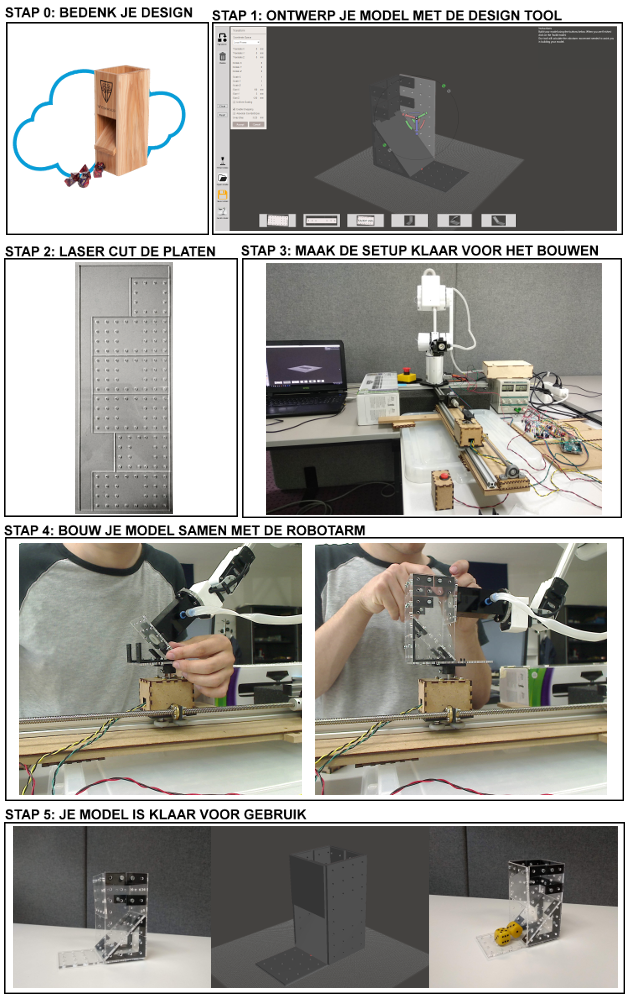
Een visuele voorstelling van de stappen die je doorloopt met het systeem, kan je zien in figuur 1.
Het begint allemaal met een idee wat je tot leven wilt brengen. In dit voorbeeld een ‘dice tower’.
De eerste stap is het maken van een 3D model, samen met mijn design tool. In deze tool kan je met behulp van platen uit een bouwpakket een 3D model opbouwen, door de platen op de juiste plaats in het model te positioneren. Er kunnen ook platen van een gekozen grootte ingevoegd worden. De design tool ondersteunt platen onder een hoek van 45, 90 of 135 graden, met behulp van 3D geprinte hoekstukjes.
Nadat je klaar bent met het maken van je 3D model, snijd je de verschillende platen uit met een lasercutter. Hiervoor maakt het systeem automatisch een bestand aan, dat rechtstreeks gebruikt kan worden door de lasercutter.
Daarna leg je de platen, hoekstukjes, bouten en moeren klaar bij de robotarm. Nu heb je alles ter beschikking om samen met de robotarm je 3D model op te bouwen. Hiervoor worden in de design tool automatisch instructies voor de robotarm berekend, op basis van je 3D model. De tool zal je tijdens het bouwen instructies geven.
Samen met de robotarm ga je stap voor stap het model opbouwen. In de design tool krijg je te zien waar je ieder hoekstukje moet plaatsen, voordat de robotarm de volgende plaat mag brengen. Het platform waarop je het model bouwt zal naar de juiste positie bewegen. De robotarm zal de volgende plaat opnemen en deze op de juiste plaats tegen het model houden. Hierdoor kan je met beide handen de plaat vastmaken aan de hoekstukjes.
Wanneer alle stappen doorlopen zijn, kan je het model van het platform nemen en is het klaar om te gebruiken.
SAMEN STERK WERK
Het doel van mijn systeem is om aan te tonen dat je samen met een robotarm aan een model kan werken. De bijhorende design tool maakt het mogelijk om een 3D model te maken, zonder dat je kennis moet hebben van 3D modelleren. De robot zal je tijdens het opbouwen van je eigen model helpen, door de platen van het model op de juiste plaats vast te houden. Hierdoor kan jij zelf met twee handen het model monteren.
“Het voelt echt aan alsof je een derde hand hebt die je helpt tijdens het bouwen”, zoals een van de deelnemers omschreef tijdens de gebruikersstudie van mijn systeem.
Figuur 1: Stappen in het proces
Bibliografie
@misc{EmpiraSoftwareGmbH,
author = {{empira Software GmbH}},
title = {{PDFsharp {\&} MigraDoc}},
url = {http://www.pdfsharp.net/},
urldate = {2018-06-06}
}
@misc{TechSmith2018,
author = {TechSmith},
title = {{Usability testing with Morae}},
url = {https://www.techsmith.com/morae.html},
urldate = {2018-06-04},
year = {2018}
}
@article{InternationalFederationofRobotics2016,
author = {{International Federation of Robotics}},
doi = {ISO 8373:2012},
file = {:C$\backslash$:/Users/Bram/AppData/Local/Mendeley Ltd./Mendeley Desktop/Downloaded/IFR - 2016 - Classification of service robots by application areas.pdf:pdf},
pages = {9--12},
title = {{Service Robots - Definition and Classification WR 2016}},
url = {http://www.iso.org/iso/iso{\_}catalogue/catalogue{\_}tc/catalogue{\_}detail.htm?csnumber=55890. https://ifr.org/img/office/Service{\_}Robots{\_}2016{\_}Chapter{\_}1{\_}2.pdf},
year = {2016}
}
@article{IFR2016,
abstract = {1.2.1 Definition (ISO 8373:2012) and delimitation The annual surveys carried out by IFR focus on the collection of yearly statistics on the production, imports, exports and domestic installations/shipments of industrial robots (at least three or more axes) as described in the ISO definition given below. Figures 1.1 shows examples of robot types which are covered by this definition and hence included in the surveys. A robot which has its own control system and is not controlled by the machine should be included in the statistics, although it may be dedicated for a special machine. Other dedicated industrial robots should not be included in the statistics. If countries declare that they included dedicated industrial robots, or are suspected of doing so, this will be clearly indicated in the statistical tables. It will imply that data for those countries is not directly comparable with those of countries that strictly adhere to the definition of multipurpose industrial robots. Wafer handlers have their own control system and should be included in the statistics of industrial robots. Wafers handlers can be articulated, cartesian, cylindrical or SCARA robots. Irrespective from the type of robots they are reported in the application " cleanroom for semiconductors " . Flat panel handlers also should be included. Mainly they are articulated robots. Irrespective from the type of robots they are reported in the application " cleanroom for FPD " . Examples of dedicated industrial robots that should not be included in the international survey are: Equipment dedicated for loading/unloading of machine tools (see figure 1.3). Dedicated assembly equipment, e.g. for assembly on printed circuit boards (see figure 1.3). Integrated Circuit Handlers (pick and place) Automated storage and retrieval systems Automated guided vehicles (AGVs) (see " World Robotics Service Robots ") The submission of statistics on industrial robots is mandatory for IFR member associations. In some countries, however, data is also collected on all types of manipulating industrial robots, that is, both multipurpose and dedicated manipulating industrial robots. Optionally, national robot associations may therefore also submit statistics on all types of manipulating industrial robots, which will be included in the publication World Robotics under the respective country chapter. Industrial robot as defined by ISO 8373:2012: An automatically controlled, reprogrammable, multipurpose manipulator programmable in three or more axes, which can be either fixed in place or mobile for use in industrial automation applications 26 1 Introduction},
author = {{International Federation of Robotics}},
file = {:C$\backslash$:/Users/Bram/AppData/Local/Mendeley Ltd./Mendeley Desktop/Downloaded/IFR - 2012 - Industrial robots -definition and classification.pdf:pdf},
pages = {25--34},
title = {{Industrial robots - definition and classification}},
url = {https://ifr.org/img/office/Industrial{\_}Robots{\_}2016{\_}Chapter{\_}1{\_}2.pdf},
year = {2016}
}
@techreport{ISO/TC2992012,
abstract = {ISO 8373:2012 defines terms used in relation with robots and robotic devices operating in both industrial and non-industrial environments.},
author = {{ISO/TC 299}},
title = {{ISO 8373:2012 - Robots and robotic devices -- Vocabulary}},
url = {https://www.iso.org/standard/55890.html},
year = {2012}
}
@article{Neto2010,
abstract = {Today, most industrial robots are still programmed using the typical teaching process, through the use of the robot teach pendant. This paper presents a robotic system that allows users, especially non-expert programmers, to instruct and program a robot just showing it what it should do, and with a high-level of abstraction from the robot language. This is done using the two most natural human interfaces (gestures and speech), a force control system and several code generation techniques. Special attention will be given to the recognition of gestures, where the data extracted from a motion sensor (3-axis accelerometer) embedded in the Wii Remote Controller was used to capture human hand behaviours. Gestures (dynamic hand positions) as well as manual postures (static hand positions) are recognized using a statistical approach and Artificial Neural Networks (ANNs). Several experiments are done to evaluate the proposed system in a non-controlled environment and to compare its performance with a similar approach, which instead of gestures uses a manual guidance system based on a force control strategy. Finally, different demonstrations with two different robots are presented, showing that the developed system can be customized for different users and robotic platforms.},
author = {Neto, Pedro and Pires, J Norberto and Moreira, A Paulo},
file = {:C$\backslash$:/Users/Bram/AppData/Local/Mendeley Ltd./Mendeley Desktop/Downloaded/Neto, Pires, Moreira - 2010 - High-level programming and control for industrial robotics using a hand-held accelerometer-based input dev.pdf:pdf},
journal = {Industrial Robot: An International Journal},
number = {2},
pages = {137--147},
title = {{High-level programming and control for industrial robotics: using a hand-held accelerometer-based input device for gesture and posture recognition}},
url = {https://arxiv.org/ftp/arxiv/papers/1309/1309.2093.pdf},
volume = {37},
year = {2010}
}
@article{Foit2017,
abstract = {Industrial robots are widely used in mass production, successfully replacing the workers during repetitive tasks. The lack of direct human participation in the production process involves the necessity of programming of the machines, which is mostly the time-consuming process. Most of the operations are well described in the process documentation, but some actions require the use of complicated paths, like for example welding, laser or water cutting, edge grinding, application of liquid sealants or films of paint etc. All of the mentioned activities need the precise movements of robot's effector and this is - in many cases - connected with the necessity of entering of many points that approximate the path. One of the ways to solve this problem is the possibility of generating the complex path automatically, using the information from the technical documentation. This paper presents such approach that uses the CAD drawings as a data source. The available literature presents this problem mainly in the aspects of large software applications, but this paper was focused on presenting the problems of the proper analysis of the drawing and how to process the data to the form that can be used during robot programming.},
author = {Foit, Krzysztof and {\'{C}}wik{\l}a, Grzegorz},
doi = {10.1051/matecconf/20179405002},
editor = {Oancea, G. and Drăgoi, M.V.},
file = {:C$\backslash$:/Users/Bram/AppData/Local/Mendeley Ltd./Mendeley Desktop/Downloaded/Foit, {\'{C}}wik{\l}a - 2017 - The CAD drawing as a source of data for robot programming purposes – a review.pdf:pdf},
journal = {MATEC Web of Conferences},
month = {jan},
pages = {05002},
publisher = {EDP Sciences},
title = {{The CAD drawing as a source of data for robot programming purposes – a review}},
url = {http://www.matec-conferences.org/10.1051/matecconf/20179405002},
volume = {94},
year = {2017}
}
@article{Neto2012,
abstract = {Purpose – The purpose of this paper is to present a CAD‐based human‐robot interface that allows non‐expert users to teach a robot in a manner similar to that used by human beings to teach each other.Design/methodology/approach – Intuitive robot programming is achieved by using CAD drawings to generate robot programs off‐line. Sensory feedback allows minimization of the effects of uncertainty, providing information to adjust the robot paths during robot operation.Findings – It was found that it is possible to generate a robot program from a common CAD drawing and run it without any major concerns about calibration or CAD model accuracy.Research limitations/implications – A limitation of the proposed system has to do with the fact that it was designed to be used for particular technological applications.Practical implications – Since most manufacturing companies have CAD packages in their facilities today, CAD‐based robot programming may be a good option to program robots without the need for skilled robot ...},
author = {Neto, Pedro and Mendes, Nuno and Ara{\'{u}}jo, Ricardo and {Norberto Pires}, J. and {Paulo Moreira}, A.},
doi = {10.1108/01439911211217125},
file = {:E$\backslash$:/School/School Uhasselt Master/Masterjaar 2/Masterproef/Research/Related work/robot programming/1309.2086.pdf:pdf},
journal = {Industrial Robot: An International Journal},
month = {apr},
number = {3},
pages = {294--303},
publisher = {Emerald Group Publishing Limited},
title = {{High‐level robot programming based on CAD: dealing with unpredictable environments}},
url = {https://www.emeraldinsight.com/doi/10.1108/01439911211217125},
volume = {39},
year = {2012}
}
@article{Neto2013,
abstract = {This paper focuses on intuitive and direct off-line robot programming from a CAD drawing running on a common 3-D CAD package. It explores the most suitable way to represent robot motion in a CAD drawing, how to automatically extract such motion data from the drawing, make the mapping of data from the virtual (CAD model) to the real environment and the process of automatic generation of robot paths/programs. In summary, this study aims to present a novel CAD-based robot programming system accessible to anyone with basic knowledge of CAD and robotics. Experiments on different manipulation tasks show the effectiveness and versatility of the proposed approach. {\textcopyright} 2013 Elsevier B.V. All rights reserved.},
author = {Neto, Pedro and Mendes, Nuno},
doi = {10.1016/j.robot.2013.02.005},
file = {:E$\backslash$:/School/School Uhasselt Master/Masterjaar 2/Masterproef/Research/Related work/robot programming/1-s2.0-S0921889013000419-main.pdf:pdf},
issn = {09218890},
journal = {Robotics and Autonomous Systems},
keywords = {CAD,Intuitive robot programming,Off-line programming},
month = {aug},
number = {8},
pages = {896--910},
publisher = {North-Holland},
title = {{Direct off-line robot programming via a common CAD package}},
url = {https://www.sciencedirect.com/science/article/pii/S0921889013000419},
volume = {61},
year = {2013}
}
@article{Baizid2016,
abstract = {a b s t r a c t This paper presents Industrial Robotics Simulation Design Planning and Optimization platform named IRoSim, which is based on SolidWorks Application Programming Interface (API) to offer an intuitive and convertible environment for designing and simulating robotized tasks. The core idea is to integrate features of mechanical CAD and robotics CAD into the same platform to facilitate the development process through the designed Graphical User Interface (GUI) which permits user friendly interaction. The platform includes various 3D models that are essential for developing any robotized task and offers possibility to integrate new models in simulation. Robotic manipulator library is one such example which contains several types of serial arms with different combinations of revolute and prismatic joints. The platform provides most important steps such as defining the task, CAD learning of the end-effector's trajectory, checking the manipulator's reachability to perform a task, simulating the motion and finally validating the manipulator's trajectory to avoid possible collisions. To demonstrate the efficiency of the proposed approach, two frequent and important tasks (spot welding and painting) using a 6-Degree Of Freedom (DOF) industrial robotic manipulator have been considered. The output of the proposed strategy provides collision-free trajectory of the manipulator's motion which can be directly mapped to a real site. Moreover, the approach permits addressing the problems related with the real implementation of ro-botized tasks.},
author = {Baizid, Khelifa and {\'{C}}ukovi{\'{c}}, Sa{\v{s}}a and Iqbal, Jamshed and Yousnadj, Ali and Chellali, Ryad and Meddahi, Amal and Deved{\v{z}}i{\'{c}}, Goran and Ghionea, Ionut},
doi = {10.1016/j.rcim.2016.06.003},
file = {:E$\backslash$:/School/School Uhasselt Master/Masterjaar 2/Masterproef/Research/Related work/robot programming/1-s2.0-S0736584515300284-main.pdf:pdf},
journal = {Robotics and Computer-Integrated Manufacturing},
title = {{IRoSim: Industrial Robotics Simulation Design Planning and Optimization platform based on CAD and knowledgeware technologies}},
url = {http://daneshyari.com/article/preview/413928.pdf},
volume = {42},
year = {2016}
}
@misc{CommonplaceRobotics2016,
author = {{Commonplace Robotics}},
file = {:C$\backslash$:/Users/Bram/AppData/Local/Mendeley Ltd./Mendeley Desktop/Downloaded/Commonplace Robotics - 2016 - Robot Interface CRI.pdf:pdf},
pages = {8},
title = {{Robot Interface CRI}},
url = {http://www.cpr-robots.com/download/CRI/CPR{\_}RobotInterfaceCRI.pdf},
year = {2016}
}
@misc{CommonplaceRobotics2018,
author = {{Commonplace Robotics}},
title = {{CPRog Updates - CPR-robots wiki}},
url = {http://wiki.cpr-robots.com/index.php?title=CPRog{\_}Updates},
urldate = {2018-05-01},
year = {2018}
}
@article{Hayes2003,
abstract = {In this paper the singular configurations of wrist-partitioned 6R serial robots in gen-eral, and the KUKA KR-15/2 industrial robot in particular, are analytically described and classified. While the results are not new, the insight provided by the geometric analysis for users of such robots is. Examining the problem in the joint axis parameter space, it is shown that when the end-effector reference point is taken to be the wrist centre the determinant of the associated Jacobian matrix splits into four factors, three of which can vanish. Two of the three potentially vanishing factors give a complete de-scription of the positioning singularities and the remaining one a complete description of the orientation singularities, in turn providing a classification scheme. ConfigurationsSingul{\`{i}} eres des Robots S{\'{e}}riel a Poignet Sph{\'{e}}rique et Six Couples Rot{\"{o}}ides: une Perspective G{\'{e}}om{\'{e}}trique pour les Utilisateurs R{\'{e}}sum{\'{e}} Dans cet article les configurations singuli{\'{e}}res des robots s{\'{e}}riel a poignet sph{\'{e}}rique et six couples rot{\"{o}}ides en g{\'{e}}n{\'{e}}ral, et celle du robot industriel KUKA KR-15/2 en particulier, sont analytiquement d{\'{e}}crites et classifi{\'{e}}es. Bien que les r{\'{e}}sultats ne soient pas nouveaux, la perspective fournie par l'analyse g{\'{e}}om{\'{e}}trique pour des utilisateurs de tels robots l'est. En examinant leprob{\`{i}} eme dans l'espace commun depara etre d'axe, on montre que quand le point de r{\'{e}}f{\'{e}}rence terminal est pris comm{\'{e}} etant le centre du poignet le d{\'{e}}terminant de la matrice associ{\'{e}}e du Jacobian se divise en quatre facteurs, dont trois peuvent dispar{\^{a}} itre. Deux des trois facteurs qui peuvent potentiellement dispar{\^{a}} itre donnent une descriptioncomp{\`{i}} ete des singularit{\'{e}}s de positionnement et les autres une descriptioncomp{\`{i}} ete des singularit{\'{e}}s d'orientation, fournissant ainsi une m{\'{e}}thode de classification.},
author = {Hayes, M J D and Husty, M L and Zsombor-Murray, P J},
file = {:C$\backslash$:/Users/Bram/AppData/Local/Mendeley Ltd./Mendeley Desktop/Downloaded/Hayes, Husty, Zsombor-Murray - 2003 - Singular Configurations of Wrist-Partitioned 6R Serial Robots a Geometric Perspective for Users.pdf:pdf},
journal = {Transactions of the Canadian Society for Mechanical Engineering},
number = {1},
pages = {15},
title = {{Singular Configurations of Wrist-Partitioned 6R Serial Robots: a Geometric Perspective for Users}},
url = {http://faculty.mae.carleton.ca/John{\_}Hayes/Papers/KR15SingCSME.pdf},
volume = {26},
year = {2003}
}
@article{ANSI1999,
author = {ANSI and RIA},
file = {:C$\backslash$:/Users/Bram/AppData/Local/Mendeley Ltd./Mendeley Desktop/Downloaded/ANSI, RIA - 1999 - American National Standard for Industrial Robots and Robot Systems — Safety Requirements Robotic Industries Associati.pdf:pdf},
journal = {.},
pages = {75},
title = {{American National Standard for Industrial Robots and Robot Systems — Safety Requirements Robotic Industries Association}},
url = {http://www.paragonproducts-ia.com/documents/RIA R15{\_}06-1999.pdf},
year = {1999}
}
@misc{Auawise,
abstract = {An image showing all three axises},
author = {Auawise},
booktitle = {2010},
title = {{Wikimedia Commons: Yaw, Roll, Pitch image}},
url = {https://commons.wikimedia.org/wiki/File:Yaw{\_}Axis{\_}Corrected.svg{\#}metadata},
urldate = {2018-04-29}
}
@misc{Rose2015,
abstract = {This paper describes a commonly used set of Tait-Bryan Euler angles, shows how to convert from Euler angles to a rotation matrix and back, how to rotate objects in both the forward and reverse direction, and how to concatenate multiple rotations into a single rotation matrix.
The paper is divided into two parts. Part 1 provides a detailed explanation of the relevant assumptions, conventions and math. Part 2 provides a summary of the key equations, along with sample code in Java. (See the links at the top of the page.)},
author = {Rose, D.},
title = {{Rotations in Three-Dimensions: Euler Angles and Rotation Matrices}},
url = {http://danceswithcode.net/engineeringnotes/rotations{\_}in{\_}3d/rotations{\_}in{\_}3d{\_}part1.html},
urldate = {2018-04-29},
year = {2015}
}
@article{Weisstein,
abstract = {According to Euler's rotation theorem, any rotation may be described using three angles. If the rotations are written in terms of rotation matrices D, C, and B, then a general rotation A can be written as A=BCD. (1) The three angles giving the three rotation matrices are called Euler angles. There are several conventions for Euler angles, depending on the axes about which the rotations are carried out. Write the matrix A as A=[a{\_}(11) a{\_}(12) a{\_}(13); a{\_}(21) a{\_}(22) a{\_}(23); a{\_}(31) a{\_}(32)...},
author = {Weisstein, Eric W.},
keywords = {15A04,51M,Mathematics:Geometry:Transformations:Rotations},
publisher = {Wolfram Research, Inc.},
title = {{Euler Angles}},
url = {http://mathworld.wolfram.com/EulerAngles.html}
}
@misc{Hofstede,
author = {Hofstede, Casper},
booktitle = {2016},
title = {{Arduino Braccio Robot Arm, Raspberry Pi Controlled with Arduino and SSC-32 – Portfolio C.M.Hofstede}},
url = {http://www.cmhofstede.nl/hobby-vrije-tijd/arduino-braccio-robot-arm-ras…},
urldate = {2018-04-22}
}
@misc{RepRap2018,
author = {RepRap},
title = {{NEMA 17 Stepper motor - RepRapWiki}},
url = {http://reprap.org/wiki/NEMA{\_}17{\_}Stepper{\_}motor},
urldate = {2018-04-21},
year = {2018}
}
@article{MicrochipTechnology2007,
author = {{Microchip Technology}},
file = {:C$\backslash$:/Users/Bram/AppData/Local/Mendeley Ltd./Mendeley Desktop/Downloaded/Microchip Technology - 2007 - MCP23017MCP23S17 16-Bit IO Expander with Serial Interface.pdf:pdf},
title = {{MCP23017/MCP23S17: 16-Bit I/O Expander with Serial Interface}},
url = {https://cdn-shop.adafruit.com/datasheets/mcp23017.pdf},
year = {2007}
}
@misc{Schmalz2018,
abstract = {Um projeto de Motor de Stepper de Motor de C{\'{o}}digo Aberto},
author = {Schmalz, Brian},
title = {{Easy Driver Stepper Motor Driver}},
url = {http://www.schmalzhaus.com/EasyDriver/index.html},
year = {2010}
}
@misc{Thingiverse,
author = {Thingiverse, Ctheroux},
booktitle = {2016},
title = {{Customizable Small Linear Carriage Generator by ctheroux - Thingiverse}},
url = {https://www.thingiverse.com/thing:1515341},
urldate = {2018-04-18}
}
@misc{Intertec2018,
author = {Intertec},
title = {{Electromagnet magnetic (disconnected) 15 N 12 Vdc 1.8 W from Conrad Electronic UK}},
url = {https://www.conrad-electronic.co.uk/ce/en/product/1218314/Electromagnet…},
urldate = {2018-04-18},
year = {2018}
}
@misc{UniversalRobotics2018,
author = {{Universal Robotics}},
title = {{Collaborative Industrial Robotic robot Arms | Cobots from UR}},
url = {https://www.universal-robots.com/},
urldate = {2018-04-14},
year = {2018}
}
@misc{RethinkRobotics2018,
author = {{Rethink Robotics}},
title = {{Baxter Collaborative Robots for Industrial Automation | Rethink Robotics}},
url = {http://www.rethinkrobotics.com/baxter/},
urldate = {2018-04-14},
year = {2018}
}
@misc{KUKA2018,
abstract = {The LBR iiwa is the world's first series-produced sensitive, and therefore HRC-compatible, robot. LBR stands for “Leichtbauroboter” (German for lightweight robot), iiwa for “intelligent industrial work assistant”. This signals the beginning of a new era in industrial, sensitive robotics – and lays the foundations for innovative and sustainable production processes. For the first time, humans and robots can work together on highly sensitive tasks in close cooperation. This opens up the possibility of new applications and the way is paved for greater cost-effectiveness and utmost efficiency. The collaborative and sensitive LBR iiwa robot is available in two versions with payload capacities of 7 and 14 kilograms.},
author = {KUKA},
title = {{LBR iiwa | KUKA AG}},
url = {https://www.kuka.com/en-be/products/robotics-systems/industrial-robots/…},
urldate = {2018-04-14},
year = {2018}
}
@inproceedings{Hermann2016,
abstract = {Although Industrie 4.0 is currently a top priority for many companies, research centers, and universities, a generally accepted definition of the term does not exist. As a result, discussing the topic on an academic level is difficult, and so is implementing Industrie 4.0 scenarios. Based on a literature review, the paper provides a definition of Industrie 4.0 and identifies six design principles for its implementation: interoperability, virtualization, decentralization, real-time capability, service orientation, and modularity. Taking into account these principles, academics may be enabled to further investigate on the topic, while practitioners may find assistance in implementing appropriate scenarios},
archivePrefix = {arXiv},
arxivId = {arXiv:1011.1669v3},
author = {Hermann, Mario and Pentek, Tobias and Otto, Boris},
booktitle = {Proceedings of the Annual Hawaii International Conference on System Sciences},
doi = {10.1109/HICSS.2016.488},
eprint = {arXiv:1011.1669v3},
file = {:E$\backslash$:/School/School Uhasselt Master/Masterjaar 2/Masterproef/Research/Human robot collaboration/Papers/Design-Principles-for-Industrie-4{\_}0-Scenarios.pdf:pdf},
isbn = {9780769556703},
issn = {15301605},
keywords = {Case Study,Design Principles,Industrie 4.0,Industry 4.0,Internet of Everything,Internet of Things,Smart Factory},
month = {jan},
pages = {3928--3937},
pmid = {15003161},
publisher = {IEEE},
title = {{Design principles for industrie 4.0 scenarios}},
url = {http://ieeexplore.ieee.org/document/7427673/},
volume = {2016-March},
year = {2016}
}
@article{Hayes2013,
abstract = {—We present and discuss four important yet un-derserved research questions critical to the future of shared-environment human-robot collaboration. We begin with a brief survey of research surrounding individual components required for a complete collaborative robot control system, discussing the current state of the art in Learning from Demonstration, active learning, adaptive planning systems, and intention recognition. We motivate the exploration of the presented research questions by relating them to existing work and representative use cases from the domains of construction and cooking.},
author = {Hayes, Bradley and Scassellati, Brian},
file = {:C$\backslash$:/Users/Bram/AppData/Local/Mendeley Ltd./Mendeley Desktop/Downloaded/Hayes, Scassellati - 2013 - Challenges in Shared-Environment Human-Robot Collaboration.pdf:pdf},
title = {{Challenges in Shared-Environment Human-Robot Collaboration}},
url = {https://pdfs.semanticscholar.org/19fb/e18e8da489b17ebb283ddc7e72af7c3ff…},
year = {2013}
}
@article{Umetani2014,
abstract = {This paper introduces novel interactive techniques for designing original hand-launched free-flight glider airplanes which can actually fly. The aerodynamic properties of a glider aircraft depend on their shape, imposing significant design constraints. We present a compact and efficient representation of glider aerodynamics that can be fit to real-world conditions using a data-driven method. To do so, we acquire a sample set of glider flight trajectories using a video camera and the system learns a nonlinear relationship between forces on the wing and wing shape. Our acquisition system is much simpler to construct than a wind tunnel, but using it we can efficiently discover a wing model for simple gliding aircraft. Our resulting model can handle general free-form wing shapes and yet agrees sufficiently well with the acquired airplane flight trajectories. Based on this compact aerodynamics model, we present a design tool in which the wing configuration created by a user is interactively optimized to maximize flight-ability. To demonstrate the effectiveness of our tool for glider design by novice users, we compare it with a traditional design workflow.},
author = {Umetani, Nobuyuki and Koyama, Yuki and Schmidt, Ryan and Igarashi, Takeo},
doi = {10.1145/2601097.2601129},
file = {:E$\backslash$:/School/School Uhasselt Master/Masterjaar 2/Masterproef/Research/Related work/2014{\_}siggraph{\_}GliderDesign.pdf:pdf},
journal = {ACM Transactions on Graphics},
month = {jul},
number = {4},
pages = {1--10},
publisher = {ACM},
title = {{Pteromys: interactive design and optimization of free-formed free-flight model airplanes}},
url = {http://dl.acm.org/citation.cfm?doid=2601097.2601129},
volume = {33},
year = {2014}
}
@article{Umetani2011,
abstract = {We present a novel interactive tool for garment design that enables, for the first time, interactive bidirectional editing between 2D pat-terns and 3D high-fidelity simulated draped forms. This provides a continuous, interactive, and natural design modality in which 2D and 3D representations are simultaneously visible and seamlessly maintain correspondence. Artists can now interactively edit 2D pat-tern designs and immediately obtain stable accurate feedback on-line, thus enabling rapid prototyping and an intuitive understanding of complex drape form.},
author = {Umetani, Nobuyuki and Kaufman, Danny M and Igarashi, Takeo and Grinspun, Eitan},
file = {:C$\backslash$:/Users/Bram/AppData/Local/Mendeley Ltd./Mendeley Desktop/Downloaded/Umetani et al. - 2011 - Sensitive Couture for Interactive Garment Modeling and Editing(2).pdf:pdf},
journal = {SIGGRAPH},
title = {{Sensitive Couture for Interactive Garment Modeling and Editing}},
url = {http://www.cs.columbia.edu/cg/pdfs/179-SC.pdf},
year = {2011}
}
@article{Megaro2015,
abstract = {We present an interactive design system that allows casual users to quickly create 3D-printable robotic creatures. Our approach au-tomates the tedious parts of the design process while providing ample room for customization of morphology, proportions, gait and motion style. The technical core of our framework is an effi-cient optimization-based solution that generates stable motions for legged robots of arbitrary designs. An intuitive set of editing tools allows the user to interactively explore the space of feasible de-signs and to study the relationship between morphological features and the resulting motions. Fabrication blueprints are generated au-tomatically such that the robot designs can be manufactured using 3D-printing and off-the-shelf servo motors. We demonstrate the ef-fectiveness of our solution by designing six robotic creatures with a variety of morphological features: two, four or five legs, point or area feet, actuated spines and different proportions. We validate the feasibility of the designs generated with our system through physics simulations and physically-fabricated prototypes.},
author = {Megaro, Vittorio and Thomaszewski, Bernhard and Nitti, Maurizio and Hilliges, Otmar and Gross, Markus and Coros, Stelian},
file = {:C$\backslash$:/Users/Bram/AppData/Local/Mendeley Ltd./Mendeley Desktop/Downloaded/Megaro et al. - 2015 - Interactive Design of 3D-Printable Robotic Creatures.pdf:pdf},
journal = {ACM SIGGRAPH Asia},
title = {{Interactive Design of 3D-Printable Robotic Creatures}},
url = {https://ait.ethz.ch/projects/2015/RobotDesigner/downloads/RobotDesigner…},
year = {2015}
}
@article{Mori2007,
abstract = {(a) creation (b) cut (c) adding a part (d) pull (e) result of sewing Figure 1: Designing an original plush toy using our system. The user interactively edits the 3D model on the screen using a sketching interface. Internally, the system generates 2D cloth pattern and shows the 3D model as a result of applying simple simulation to the pattern. Abstract We introduce Plushie, an interactive system that allows nonprofes-sional users to design their own original plush toys. To design a plush toy, one needs to construct an appropriate two-dimensional (2D) pattern. However, it is difficult for non-professional users to appropriately design a 2D pattern. Some recent systems auto-matically generate a 2D pattern for a given three-dimensional (3D) model, but constructing a 3D model is itself a challenge. Further-more, an arbitrary 3D model cannot necessarily be realized as a real plush toy, and the final sewn result can be very different from the original 3D model. We avoid this mismatch by constructing appro-priate 2D patterns and applying simple physical simulation to it on the fly during 3D modeling. In this way, the model on the screen is always a good approximation of the final sewn result, which makes the design process much more efficient. We use a sketching inter-face for 3D modeling and also provide various editing operations tailored for plush toy design. Internally, the system constructs a 2D cloth pattern in such a way that the simulation result matches the user's input stroke. Our goal is to show that relatively simple algo-rithms can provide fast, satisfactory results to the user whereas the pursuit of optimal layout and simulation accuracy lies outside this paper's scope. We successfully demonstrated that non-professional users could design plush toys or balloon easily using Plushie.},
author = {Mori, Yuki and Igarashi, Takeo},
doi = {10.1145/1239451.1239496},
file = {:C$\backslash$:/Users/Bram/AppData/Local/Mendeley Ltd./Mendeley Desktop/Downloaded/Mori, Igarashi - 2007 - Plushie An Interactive Design System for Plush Toys.pdf:pdf},
journal = {ACM Trans. Graph. Article},
number = {10},
title = {{Plushie: An Interactive Design System for Plush Toys}},
url = {http://doi.acm.org/10.1145/1239451.12},
volume = {26},
year = {2007}
}
@article{Lipton,
abstract = {— Despite the ubiquity of carpentered items, the customization of carpentered items remains labor intensive. The generation of laymen editable templates for carpentry is difficult. Current design tools rely heavily on CNC fabrication, limiting applicability. We develop a template based system for carpentry and a robotic fabrication system using mobile robots and standard carpentry tools. Our end-to-end design and fabrication tool democratizes design and fabrication of carpentered items. Our method combines expert knowledge for template design, allows laymen users to customize and verify specific designs, and uses robotics system to fabricate parts. We validate our system using multiple designs to make customizable, verifiable templates and fabrication plans and show an end-to-end example that was designed, manufactured, and assembled using our tools.},
author = {Lipton, Jeffrey I and Schulz, Adriana and Spielberg, Andrew and Trueba, Luis and Matusik, Wojciech and Rus, Daniela},
file = {:E$\backslash$:/School/School Uhasselt Master/Masterjaar 2/Masterproef/Research/Human robot collaboration/Papers/Robot Assisted Carpentry for Mass Customization.pdf:pdf},
title = {{Robot Assisted Carpentry for Mass Customization}},
url = {http://people.csail.mit.edu/jlipton/PrePrint Papers/Robot Assisted Carpentry for Mass Customization.pdf}
}
@misc{CommonplaceRobotics,
author = {{Commonplace Robotics}},
keywords = {mover6{\_}robotarm},
mendeley-tags = {mover6{\_}robotarm},
title = {{Commonplace Robotics Mover6}},
url = {http://www.cpr-robots.com/products/mover6.html},
urldate = {2018-03-10}
}
@misc{Arduino,
author = {Arduino},
keywords = {braccio},
mendeley-tags = {braccio},
title = {{Tinkerkit Braccio robot}},
url = {https://store.arduino.cc/tinkerkit-braccio},
urldate = {2018-03-10}
}
@misc{Autodesk,
author = {Autodesk},
keywords = {meshmixer},
mendeley-tags = {meshmixer},
title = {{Autodesk Meshmixer}},
url = {https://www.meshmixer.com/},
urldate = {2018-03-07}
}
@article{Lafreniere2016,
abstract = {Figure 1. We explore crowdsourced fabrication through the collaborative construction of a 12-foot tall bamboo pavilion (a). The pavilion was built with the assistance of more than one hundred untrained volunteers over a 3-day exhibition, enhanced and enabled by an intelligent construction space (b). Workers were guided by smartwatch devices (c), wireless LED modules embedded in building materials (d, e), and a backend engine that coordinated the overall build process. ABSTRACT In recent years, extensive research in the HCI literature has explored interactive techniques for digital fabrication. How-ever, little attention in this body of work has examined how to involve and guide human workers in fabricating larger-scale structures. We propose a novel model of crowdsourced fabrication, in which a large number of workers and volun-teers are guided through the process of building a pre-designed structure. The process is facilitated by an intelligent construction space capable of guiding individual workers and coordinating the overall build process. More specifi-cally, we explore the use of smartwatches, indoor location sensing, and instrumented construction materials to provide real-time guidance to workers, coordinated by a foreman en-gine that manages the overall build process. We report on a three day deployment of our system to construct a 12'-tall bamboo pavilion with assistance from more than one hun-dred volunteer workers, and reflect on observations and feedback collected during the exhibit.},
author = {Lafreniere, Benjamin and Coelho, Marcelo H. and Cote, Nicholas and Li, Steven and Nogueira, Andy and Nguyen, Long and Schwinn, Tobias and Stoddart, James and Thomasson, David and Wang, Ray and White, Thomas and Grossman, Tovi and Benjamin, David and Conti, Maurice and Menges, Achim and Fitzmaurice, George and Anderson, Fraser and Matejka, Justin and Kerrick, Heather and Nagy, Danil and Vasey, Lauren and Atherton, Evan and Beirne, Nicholas},
doi = {10.1145/2984511.2984553},
file = {:E$\backslash$:/School/School Uhasselt Master/Masterjaar 2/Masterproef/Research/Human robot collaboration/Papers/Markeerde papers/Kami Export - uist3223-lafreniereA.pdf:pdf},
isbn = {9781450341899},
journal = {Proceedings of the 29th Annual Symposium on User Interface Software and Technology - UIST '16},
pages = {15--28},
title = {{Crowdsourced Fabrication}},
url = {http://dl.acm.org/citation.cfm?doid=2984511.2984553},
year = {2016}
}
@article{Makrini2017,
abstract = {Collaborative robots, the so-called cobots, that work together with the human, are becoming more and more popular in the industrial world. An example of an application where these robots are useful is the assembly task. In this case, the human and the robot complement each other. On one side, the human can achieve more dexterous tasks, while on the other side, the robot can assist the assembly process to lower the physical and cognitive work load, e.g. to avoid errors, and in the same way reduce absenteeism. This paper describes a novel collaborative architecture for human-robot assembly tasks. The developed architecture is composed of four modules; face recognition, gesture recognition and human-like robot behavior modules are used to enhance the human-robot interaction, while the visual inspection module is utilized for quality control during the assembly process. A collaborative task consisting of the assembly of a box whereby the robot assists the human was designed and implemented on the Baxter robot. This was used as the application use case to validate the developed collaborative architecture.},
author = {Makrini, Ilias El and Merckaert, Kelly and Lefeber, Dirk and Vanderborght, Bram},
doi = {10.1109/IROS.2017.8205971},
file = {:E$\backslash$:/School/School Uhasselt Master/Masterjaar 2/Masterproef/Research/Human robot collaboration/Papers/Markeerde papers/Kami Export - Design of a Collaborative Architecture for Human-Robot Assembly Tasks.pdf:pdf},
isbn = {9781538626825},
issn = {21530866},
journal = {IEEE International Conference on Intelligent Robots and Systems},
keywords = {collaborative architecture,face recognition,gesture recognition,human-robot assembly,visual inspection},
pages = {1624--1629},
title = {{Design of a collaborative architecture for human-robot assembly tasks}},
volume = {2017-Septe},
year = {2017}
}