Storend licht wordt meetlat voor het heelal
Ergens in het heelal botsen twee zwarte gaten in elkaar. Ze versmelten in een fractie van een seconde en zenden daarbij meer energie de ruimte in dan alle sterren in het zichtbare heelal samen. Tegen de tijd dat die klap de Aarde bereikt, is er nog maar een rimpeling in de ruimte over die kleiner is dan een duizendste van de doorsnede van een proton. Ingenieur Arthur Callens (UGent) onderzocht een nieuwe manier om te controleren of de detector die deze rimpelingen opvangt wel correct meet, door een storend lichteffect bewust op te wekken en te gebruiken als meetlat.
Een lek dat telt

Sinds de eerste meting van zo’n botsing in 2015 hebben zwaartekrachtsdetectoren al honderdtallen keren dit soort kosmische klappen opgevangen. Dat gebeurt binnen een internationale samenwerking van meer dan 1500 wetenschappers wereldwijd, waarbinnen Callens zijn thesis uitvoerde. De Virgo-detector in Italië, een van die instrumenten, bestaat uit twee armen (laserbuizen) van 3 kilometer lang. Een lichtstraal kaatst er zowat driehonderd keer heen en weer. Die armen worden telkens wat langer of korter door een passerende zwaartekrachtsgolf. Uit die piepkleine lengteverandering berekent Virgo de massa, afstand en locatie van botsende zwarte gaten of neutronensterren. Maar die berekening staat of valt met de ijking van het instrument: hoe goed we weten hoe de ruwe meting zich verhoudt tot de werkelijke rek in de ruimte. Een fout in die ijking betekent een fout op elke afstand die Virgo meet, ook de afstanden die gebruikt worden om te berekenen hoe snel het heelal uitdijt.
Aan het einde van elke arm zit een spiegel die bijna, maar niet helemaal, perfect reflecteert. Een piepklein deel van het licht, amper drie miljoenste, lekt erdoorheen. Dat lek is nuttig: het voedt controle-fotodiodes, maar het is ook al jaren een bron van ergernis voor de mensen die de detector draaiende houden. Als dat lekkende licht ergens achter de spiegel weerkaatst en opnieuw de arm binnendringt, kan het zich voordoen als een echte zwaartekrachtsgolf en de meting verstoren.
Van storing tot signaal
In 2021 kregen Virgo-onderzoekers een idee: in plaats van dat verstoorde licht alleen te bestrijden, konden ze het ook gebruiken. Het natuurlijke trillen van de opstelling achter de spiegel, veroorzaakt door gewone seismische ruis, verstrooit licht terug de arm in op een manier die afhangt van net dat spiegellek. Meet je dat verstrooide signaal nauwkeurig genoeg, dan kan je het spiegellek zelf berekenen. Dit kan gebruikt worden als een onafhankelijke controle op de optica van de detector en dus als ijking ervan.
Dat idee kan in praktijk gebracht worden: een klein piëzo-elektrisch plaatje dat op een gekozen frequentie heen en weer buigt en zo doelbewust verstrooid licht opwekt, in plaats van te wachten op toevallige trillingen. Callens testte die opstelling in het lab en bouwde een gedetailleerde simulatie om te bewijzen dat het concept ook echt werkt. Twee sensoren meten de flikkering die daardoor ontstaat: een bij het plaatje zelf (om te meten hoeveel verstrooid licht aanwezig is) en een aan het einde van de detector (om te meten hoe de detector reageert op dit verstrooid licht). Omdat beide signalen op een net iets andere manier afhangen van het spiegellek, kan je ze samen gebruiken en een zelfijkende methode bekomen.
Enkel op het juiste moment
Het piëzo-plaatje komt terecht op de eindbank van Virgo, net achter de eindspiegel aan het uiteinde van elke arm: exact waar het lekkende licht toch al naartoe gaat. Vandaar kan het gericht verstrooid licht de arm insturen zonder dat er iets aan de rest van de detector hoeft te veranderen.

Maar dat lukt niet om het even wanneer. Het plaatje is aan één kant vastgeklemd, zoals een duikplank: wanneer de punt uitwijkt, kantelt het meteen ook een beetje mee. Bij de minste kanteling mist het weerkaatste licht de arm en gaat het verloren. Alleen op het exacte moment dat het plaatje door zijn rustpositie zwiept, twee keer per trilling, staat het weer helemaal recht en vindt het licht zijn weg terug naar binnen. Het bruikbare signaal bestaat dus alleen in flitsen van een fractie van een seconde, telkens rond dat ene nulpunt. 
En ondanks die krappe tijdsvensters haalt de methode in simulatie een nauwkeurigheid van ruim onder een procent, over een enorm bereik van trilfrequenties: van eens per duizend seconden tot vijftig keer per seconde.
Terug naar de werkbank
Callens bouwde en testte ook een prototype van het echte plaatje en zijn positioneersysteem, klaar voor installatie op Virgo. Die tests brachten meteen een onverwacht probleem aan het licht: het kale oppervlak van het plaatje absorbeert bijna al het invallende laserlicht en warmt daardoor gevaarlijk op in de vacuümomgeving waarin het moet werken. De oplossing, een dun reflecterend laagje, zou meteen ook het meetsignaal versterken. Een laagje spectralon (de vooropgestelde oplossing) zou tevens de bruikbare hoek van het piëzo-plaatje verhogen. Het is een van de praktische stappen die nog moeten gebeuren voor de echte inzet: het plaatje ijken op een onafhankelijke sensor, de vacuümbestendigheid bevestigen, en uiteindelijk een testmeting uitvoeren op de detector zelf. 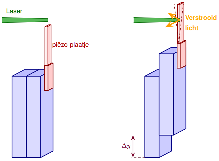
Eenmaal geïnstalleerd, levert deze methode iets wat geen enkele bestaande ijkingstechniek alleen kan: een volledig onafhankelijke controle over een breed frequentiebereik, naast twee andere methodes die elk hun eigen blinde vlek hebben. Overeenstemming tussen onafhankelijke ijkingsmethoden is precies hoe precisiewetenschap vertrouwen opbouwt, en hoe klein deze bijdrage ook lijkt, ze maakt elke toekomstige ontdekking van Virgo een beetje betrouwbaarder.
Ergens in het heelal botsen twee zwarte gaten in elkaar. Wanneer hun rimpeling ooit de Aarde bereikt, hangt alles af van de meetlat die haar opvangt. Dankzij dit onderzoek staat die meetlat een fractie strakker.
Bibliografie
[1] D. Estevez, P. Lagabbe, A. Masserot, L. Rolland, M. Seglar-Arroyo, and D. Verkindt, “The Advanced Virgo photon calibrators,”
Classical
and Quantum Gravity, vol. 38, p. 075007, 2021.
[2] B. P. Abbott
et al., “Observation of gravitational waves from a binary black hole merger,”
Phys. Rev. Lett., vol. 116, p. 061102, Feb.
2016.
[3] F. Acernese
et al., “Interferometer Sensing and Control for the Advanced Virgo Experiment in the O3 Scientific Run,”
Galaxies, vol. 8,
no. 4, p. 85, 2020.
[4] B. P. Abbott
et al., “A gravitational-wave standard siren measurement of the Hubble constant,”
Nature, vol. 551, pp. 85–88, 2017.
[5] M. Was, R. Gouaty, and R. Bonnand, “End benches scattered light modelling and subtraction in advanced virgo,”
Classical and Quan-
tum Gravity, vol. 38, p. 075020, mar 2021.
[6] A. Freise and K. Strain, “Interferometer techniques for gravitational-wave detection,”
Living Reviews in Relativity, vol. 13, Feb. 2010.
[7] D. Baumann, “General relativity.” Lecture notes, Institute of Theoretical Physics, University of Amsterdam.
[8] The Virgo Collaboration, “Overview of Advanced Virgo Plus Phase II ,” Official Document VIR-1179C-19, Virgo Collaboration, Nov. 2019.
[9] M. Was, “Laser power and SR transmission choice for O4,” Advanced Virgo Activity Report VIR-0406A-19, Virgo Collaboration, Apr.
2019. Internal LKV document. https://tds.virgo-gw.eu/ql/?c=14234.
[10] Virgo Collaboration, “Advanced virgo plus for o5 – technical design report,” Technical Report VIR-0499A-25, Virgo Collaboration,
May 2025. Release A, accessed May 2026.
[11] A. Allocca, D. Bersanetti, J. Casanueva Diaz, C. De Rossi, M. Mantovani, A. Masserot, L. Rolland, P. Ruggi, B. Swinkels, E. N. Tapia
San Martin, M. Vardaro, and M. Was, “Interferometer sensing and control for the advanced virgo experiment in the o3 scientific run,”
Galaxies, vol. 8, no. 4, 2020.
[12] C. Mueller, “The Advanced LIGO input mode cleaner,” Presentation, Detector Characterization Meeting G1400096, LIGO Scientific
Collaboration, Feb. 2014.
[13] Y. Akiyama
et al., “Vibration isolation system with a compact damping system for power recycling mirrors of KAGRA,”
Class. Quantum
Grav., 2019.
[14] F. Acernese
et al., “Advanced virgo: a second-generation interferometric gravitational wave detector,”
Classical and Quantum Grav-
ity, vol. 32, p. 024001, dec 2014.
[15] F. Bondu, “Dark fringe shot noise sensitivity,” Virgo Note VIR-NOT-OCA-1390-243, Virgo Collaboration, Apr. 2003. https://tds.
virgo-gw.eu/ql/?c=1451.
[16] B. Swinkels, “Requirements on sensing noise for the Pound-Drever-Hall technique for the lock of the arm-cavities,” Virgo Note
VIR-0467A-12, Virgo Collaboration, Dec. 2012. Internal LKV document. https://tds.virgo-gw.eu/ql/?c=9290.
[17] ESPCI, “Measurements on the beamsplitter substrate,” Virgo Note VIR-NOT-ESP-1390-77, Virgo Collaboration, Jan. 1997. https:
//tds.virgo-gw.eu/ql/?c=85.
[18] L. Pinard, “Advanced Virgo beam splitter characterization report — BS02 (coatings C14041+C14045),” Specification/Characterisation
VIR-0446B-14, Virgo Collaboration, Nov. 2014. Internal Virgo document. https://tds.virgo-gw.eu/ql/?c=10497.
[19] T. T. Fricke, N. D. Smith-Lefebvre, R. Abbott, R. Adhikari, K. L. Dooley, M. Evans, P. Fritschel, V. V. Frolov, K. Kawabe, J. S. Kissel, B. J. J.
Slagmolen, and S. J. Waldman, “DC readout experiment in Enhanced LIGO,”
Class. Quantum Grav., vol. 29, no. 6, p. 065005, 2012.
[20] F. Acernese, M. Agathos, K. Agatsuma, D. Aisa, N. Allemandou, A. Allocca, J. Amarni, P. Astone, G. Balestri, G. Ballardin, F. Barone, J.-P.
Baronick, M. Barsuglia, A. Basti, F. Basti, T. Bauer, V. Bavigadda, M. Bejger, M. Beker, and J.-P. Zendri, “Advanced virgo: A second-
generation interferometric gravitational wave detector,”
Classical and Quantum Gravity, vol. 32, 01 2015.
[21] C. Jacquet, Optical Tuning Team, and Commissioning Team, “Arm cavity characterization,” Virgo Technical Document VIR-0540A-24,
Virgo Collaboration, June 2024. Presented at Virgo Week, 5th June 2024.
[22] L. Pinard, “Advanced Virgo input mirror characterization report — IM03 (coatings C118046+C18013) — spare IM,” Specifica-
tion/Characterisation VIR-0326A-23, Virgo Collaboration, Apr. 2023. Internal Virgo document. https://tds.virgo-gw.
eu/ql/?c=19196.
[23] L. Pinard, “Advanced Virgo end mirror characterization report — EM03 (coatings C14042/20 + C14035/20),” Specifica-
tion/Characterisation VIR-0270A-15, Virgo Collaboration, June 2015. Internal Virgo document. https://tds.virgo-gw.
eu/ql/?c=10991.
[24] C. Bond, D. Brown, A. Freise, and K. A. Strain, “Interferometer techniques for gravitational-wave detection,”
Living Rev. Relativ., vol. 19,
p. 3, 2016.
[25] J. Mizuno, K. A. Strain, P. G. Nelson, J. M. Chen, R. Schilling, A. Rüdiger, W. Winkler, and K. Danzmann, “Resonant sideband extraction:
a new configuration for interferometric gravitational wave detectors,”
Phys. Lett. A, vol. 175, no. 5, pp. 273–276, 1993.
[26] J. Mizuno,
Comparison of optical configurations for laser-interferometric gravitational-wave detectors. PhD thesis, Universität
Hannover, Hanover, Germany, 1995.
[27] E. Polini, “New High Finesse AdV+ Output Mode Cleaner (OMC),” Presentation, LVK Meeting VIR-0261A-21, Virgo Collaboration, Mar.
2021. Virgo Technical Document System.
[28] L. Di Gallo, “Mirror Surface Studies for Advanced Virgo OMC,” Scientific & Technical Note VIR-0267A-12, Virgo Collaboration, July 2012.
Virgo Technical Document System. Publicly available.
[29] M. Ducrot, R. Bonnand, R. Gouaty, F. Marion, A. Masserot, B. Mours, L. Rolland, and M. Was, “Measurements of Advanced Virgo OMC
Cavities Finesse,” Virgo Note VIR-0458A-14, Virgo Collaboration, Oct. 2014. Virgo Technical Document System. Publicly available.
[30] A. Di Virgilio, “Seismic and thermal noise upper limits at 10 Hz for the Virgo suspensions,” Virgo Note VIR-NOT-PIS-1390-334, Virgo
Collaboration, Dec. 2006. https://tds.virgo-gw.eu/ql/?c=1668.
[31] t. Accadia, F. Acernese, M. Alshourbagy, P. Amico, F. Antonucci, S. Aoudia, N. Arnaud, C. Arnault, K. Arun, P. Astone, S. Avino, D. Babusci,
G. Ballardin, F. Barone, G. Barrand, L. Barsotti, M. Barsuglia, A. Basti, T. Bauer, and Z. Zhang, “Virgo: A laser interferometer to detect
gravitational waves,”
Journal of Instrumentation, vol. 7, p. P03012, 03 2012.
[32] A. Basti, V. Boschi, P. Chessa, V. Dattilo, R. Passaquieti, and P. Ruggi, “The seismic isolation system of advanced virgo plus, phase ii,”
Nuclear Instruments and Methods in Physics Research Section A: Accelerators, Spectrometers, Detectors and Associated Equipment,
vol. 1048, p. 168021, 2023.
[33] P. Amico, L. Bosi, L. Carbone, L. Gammaitoni, F. Marchesoni, M. Punturo, F. Travasso, and H. Vocca, “The Advanced Virgo monolithic
fused silica suspension,”
Nucl. Instrum. Meth. A, vol. 824, pp. 644–645, 2016.
[34] G. Losurdo, M. Bernardini, S. Braccini, C. Bradaschia, C. Casciano, V. Dattilo, R. De Salvo, A. Di Virgilio, F. Frasconi, A. Gaddi, A. Gen-
nai, A. Giazotto, H. B. Pan, F. Paoletti, A. Pasqualetti, R. Passaquieti, D. Passuello, R. Taddei, and Z. Zhang, “An inverted pendulum
preisolator stage for the Virgo suspension system,”
Rev. Sci. Instrum., vol. 70, no. 5, pp. 2507–2515, 1999.
[35] G. Losurdo, G. Calamai, E. Cuoco, L. Fabbroni, G. Guidi, M. Mazzoni, R. Stanga, F. Vetrano, L. Holloway, D. Passuello, G. Ballardin,
S. Braccini, C. Bradaschia, R. Cavalieri, G. Cella, V. Dattilo, A. Di Virgilio, F. Fidecaro, F. Frasconi, A. Gennai, A. Giazotto, P. La Penna,
F. Paoletti, A. Pasqualetti, R. Passaquieti, R. Poggiani, R. Taddei, A. Viceré, and Z. Zhang, “Inertial control of the mirror suspensions
of the Virgo interferometer for gravitational wave detection,”
Rev. Sci. Instrum., vol. 72, no. 9, pp. 3653–3661, 2001.
[36] A. Allocca
et al., “Simulations for the Locking and Alignment Strategy of the DRMI Configuration of the Advanced Virgo Plus Detector,”
Galaxies, vol. 10, no. 6, p. 115, 2022.
[37] S. Hild, H. Grote, J. Degallaix, S. Chelkowski, K. Danzmann, A. Freise, M. Hewitson, J. Hough, H. Lück, M. Prijatelj, K. A. Strain, J. R. Smith,
and B. Willke, “DC-readout of a signal-recycled gravitational wave detector,”
Classical and Quantum Gravity, vol. 26, no. 5, p. 055012,
2009.
[38] R. L. Ward, R. Adhikari, B. Abbott, R. Abbott, D. Barron, R. Bork, T. Fricke, V. Frolov, J. Heefner, A. Ivanov, O. Miyakawa, K. McKenzie,
B. Slagmolen, M. Smith, R. Taylor, S. Vass, S. Waldman, and A. Weinstein, “DC readout experiment at the Caltech 40 m prototype
interferometer,”
Class. Quantum Grav., vol. 25, no. 11, p. 114030, 2008.
[39] K. Somiya, Y. Chen, S. Kawamura, and N. Mio, “Frequency noise and intensity noise of next-generation gravitational-wave detectors
with RF/DC readout schemes,”
Phys. Rev. D, vol. 73, p. 122005, 2006.
[40] C. M. Caves, “Quantum-mechanical noise in an interferometer,”
Phys. Rev. D, vol. 23, pp. 1693–1708, Apr 1981.
[41] V. B. Braginsky and F. Y. Khalili,
Quantum Measurement. Cambridge: Cambridge University Press, 1992.
[42] J. Abadie
et al., “A gravitational wave observatory operating beyond the quantum shot-noise limit,”
Nature Physics, vol. 7, p. 962–
965, Sept. 2011.
[43] G. M. Harry, H. Armandula, E. Black, D. R. M. Crooks, G. Cagnoli, J. Hough, P. Murray, S. Reid, S. Rowan, P. Sneddon, M. M. Fejer, R. Route,
and S. D. Penn, “Thermal noise in interferometric gravitational wave detectors due to dielectric optical coatings,”
Class. Quantum
Grav., vol. 19, pp. 897–917, 2002.
[44] M. Granata, A. Amato, G. Cagnoli, M. Coulon, J. Degallaix, D. Forest, L. Mereni, C. Michel, L. Pinard, B. Sassolas, and J. Teillon, “Progress in
the measurement and reduction of thermal noise in optical coatings for gravitational-wave detectors,”
Appl. Opt., vol. 59, pp. A229–
A235, 2020.
[45] S. D. Penn, G. M. Harry, A. M. Gretarsson, S. E. Kittelberger, P. R. Saulson, J. J. Schiller, J. R. Smith, and S. O. Swords, “Mechanical loss in
tantala/silica dielectric mirror coatings,”
Classical and Quantum Gravity, vol. 20, no. 13, pp. 2917–2928, 2003.
[46] S. Di Pace, “Status of advanced virgo and upgrades before next observing runs,”
Physica Scripta, vol. 96, 12 2021.
[47] S. Karki
et al., “The Advanced LIGO photon calibrators,”
Review of Scientific Instruments, vol. 87, p. 114503, 2016.
[48] F. Acernese
et al., “Calibration of Advanced Virgo and reconstruction of the detector strain h(t) during the observing run O3,”
Classical and Quantum Gravity, vol. 39, p. 045006, 2022.
[49] D. Bhattacharjee
et al., “Calibrating the global network of gravitational wave observatories via laser power calibration at NIST and
PTB,”
Metrologia, vol. 61, p. 054002, 2024.
[50] F. Aubin, E. Dangelser, D. Estevez, A. Masserot, B. Mours, T. Pradier, A. Syx, and P. V. Hove, “The Virgo Newtonian calibration system
for the O4 observing run,”
Classical and Quantum Gravity, vol. 42, p. 035007, 2025.
[51] D. Estevez, B. Mours, and T. Pradier, “Newtonian calibrator tests during the Virgo O3 data taking,”
Classical and Quantum Gravity,
vol. 38, p. 075012, 2021.
[52] H. Kogelnik and T. Li, “Laser beams and resonators,”
Applied Optics, vol. 5, no. 10, pp. 1550–1567, 1966.
[53] Wikipedia contributors, “Gaussian beam — Wikipedia, the free encyclopedia,” 2026. [Online; accessed 11-May-2026].
[54] D. Z. Anderson, “Alignment of resonant optical cavities,”
Applied Optics, vol. 23, no. 17, pp. 2944–2949, 1984.
[55] B. E. A. Saleh and M. C. Teich,
Fundamentals of Photonics. Wiley, 2nd ed., 2007.
[56] Ansys, “Fabry-perot cavity (interconnect).” https://optics.ansys.com/hc/en-us/articles/
360042323754-Fabry-Perot-cavity-INTERCONNECT, 2025. Accessed: 2026-05-11.
[57] A. E. Siegman,
Lasers. University Science Books, 1986.
[58] C. Jacquet, “Alternative method for the arms Gouy phase measurement,” Virgo Technical Document VIR-1074A-24, Virgo Collabo-
ration, Dec. 2024. Presented at the Optical Tuning Meeting, 10th December 2024.
[59] F. W. J. Olver, A. B. Olde Daalhuis, D. W. Lozier, B. I. Schneider, R. F. Boisvert, C. W. Clark, B. R. Miller, B. V. Saunders, H. S. Cohl, and M. A.
McClain, “Nist digital library of mathematical functions,” 2023. Release 1.1.10 of 2023-06-15.
[60] E. D. Black, “An introduction to Pound–Drever–Hall laser frequency stabilization,”
American Journal of Physics, vol. 69, no. 1, pp. 79–
87, 2001.
[61] R. W. P. Drever, J. L. Hall, F. V. Kowalski, J. Hough, G. M. Ford, A. J. Munley, and H. Ward, “Laser phase and frequency stabilization using
an optical resonator,”
Applied Physics B, vol. 31, no. 2, pp. 97–105, 1983.
[62] S. Bordo, “Analyse van verstrooid licht voor de kalibratie van de virgo interferometer,” master’s thesis, Universiteit Antwerpen,
Antwerp, Belgium, jun 2026.
[63] J. Degallaix, “Oscar: A matlab based package to simulate realistic optical cavities,”
SoftwareX, vol. 12, p. 100587, 2020.
[64] J. Degallaix, “Oscar a matlab based optical fft code,”
Journal of Physics: Conference Series, vol. 228, p. 012021, may 2010.
[65] Stellafane Amateur Telescope Making, “Measuring sagitta (depth of curve).” https://stellafane.org/, n.d. Accessed:
2026-05-19. Instructions on measuring mirror sagitta using mechanical methods.
[66] M. J. Lawrence, B. Willke, M. E. Husman, E. K. Gustafson, and R. L. Byer, “Dynamic response of a fabry–perot interferometer,”
J. Opt.
Soc. Am. B, vol. 16, pp. 523–532, Apr 1999.
[67] M. Rakhmanov, “Doppler-induced dynamics of fields in fabry–perot cavities with suspended mirrors,”
Applied Optics, vol. 40, p. 1942,
Apr. 2001.
[68] M. E. Zucker, “Transmission of optical power transients by Fabry–Perot cavities: Laser power stabilization and ringdown measure-
ment applications,” ligo technical memorandum, LIGO Project, Oct. 1990. 31 October 1990.
[69] M. Rakhmanov, R. L. Savage Jr., D. H. Reitze, and D. B. Tanner, “Dynamic resonance of light in Fabry–Perot cavities,”
Physics Letters
A, vol. 305, pp. 239–244, 2002.
[70] F. Bayer-Helms, “Coupling coefficients of an incident wave and the modes of a spherical optical resonator in the case of mismatching
and misalignment,”
Applied Optics, vol. 23, no. 9, pp. 1369–1380, 1984.
[71] D. Estevez, P. Lagabbe, A. Masserot, L. Rolland, M. Seglar-Arroyo, and D. Verkindt, “The Advanced Virgo photon calibrators,” Tech. Rep.
VIR-0705A-20, Virgo Collaboration, 2020.
[72] A. V. Oppenheim, A. S. Willsky, and S. H. Nawab,
Signals and Systems. Prentice Hall, 2nd ed., 1997.
[73] A. Savitzky and M. J. E. Golay, “Smoothing and differentiation of data by simplified least squares procedures,”
Analytical Chemistry,
vol. 36, no. 8, pp. 1627–1639, 1964.
[74] K. Levenberg, “A method for the solution of certain non-linear problems in least squares,”
Quarterly of Applied Mathematics, vol. 2,
no. 2, pp. 164–168, 1944.
[75] D. W. Marquardt, “An algorithm for least-squares estimation of nonlinear parameters,”
Journal of the Society for Industrial and
Applied Mathematics, vol. 11, no. 2, pp. 431–441, 1963.
[76] Thorlabs, Inc.,
PB4NB2S Piezoelectric Bimorph with Holder, 150 V, ±
450 μm Travel – Specification Sheet. Thorlabs, Inc., Newton, NJ,
USA, Feb. 2024. Document CTN010297-S01, Rev. E.
[77] Thorlabs, Inc.,
MDT693B and MDT694B Open-Loop Piezo Controllers – User Guide. Thorlabs, Inc., Newton, NJ, USA, Apr. 2023. Docu-
ment TTN011225-D02, Rev. F.
[78] Newport Corporation,
AG-LS25-27 Agilis Piezo Linear Stage, User Manual. Newport Corporation, 2023.
[79] M. Hunstig, “Piezoelectric inertia motors—a critical review of history, concepts, design, applications, and perspectives,”
Actuators,
vol. 6, no. 1, p. 7, 2017.
[80] K. Spanner and B. Koc, “Piezoelectric motors, an overview,”
Actuators, vol. 5, no. 1, p. 6, 2016.
[81] M. Hunstig, T. Hemsel, and W. Sextro, “Stick–slip and slip–slip operation of piezoelectric inertia drives—Part I: Ideal excitation,”
Sensors and Actuators A: Physical, vol. 200, pp. 79–89, 2013.
[82] M. Hunstig, T. Hemsel, and W. Sextro, “Stick–slip and slip–slip operation of piezoelectric inertia drives—Part II: Frequency-limited
excitation,”
Sensors and Actuators A: Physical, vol. 200, pp. 79–89, 2013.
[83] Z. et al., “A review of recent studies on piezoelectric stick-slip actuators,”
Precision Engineering, 2025.
[84] T. J. Kane and R. L. Byer, “Monolithic, unidirectional single-mode Nd:YAG ring laser,”
Opt. Lett., vol. 10, no. 2, pp. 65–67, 1985.
[85] Coherent, Inc.,
Mephisto/Mephisto S: Ultra-Narrow Linewidth CW DPSS Laser, 2022. Document MC-013-13-0M0522 Rev. H.
[86] F. Li, Z. Xu, X. Wei, and X. Yao, “Determination of temperature dependence of piezoelectric coefficients matrix of lead zirconate
titanate ceramics by quasi-static and resonance method,”
Journal of Physics D: Applied Physics, vol. 42, p. 095417, apr 2009.
[87] M. Boccara, J.-F. Bouchaudy, B. Mours, and F. Richard, “Ultra-high vacuum qualification of the prototype module for the 2 × 3 km
arms of the VIRGO interferometer,”
Vacuum, vol. 57, pp. 283–297, 2000.
[88] R. Lugolole and S. K. Obwoya, “The effect of thickness of aluminium films on optical reflectance,”
Journal of Ceramics, vol. 2015,
no. 1, p. 213635, 2015.
[89] M. Yang, C. Zhou, and D. Jiang, “Comparison of different strategies to realize highly reflective thin film coatings at 1064nm,”
Infrared
Physics & Technology, vol. 51, no. 6, pp. 572–575, 2008.
[90] A. D. Rakić, A. B. Djurišić, J. M. Elazar, and M. L. Majewski, “Optical properties of metallic films for vertical-cavity optoelectronic
devices,”
Applied Optics, vol. 37, pp. 5271–5283, 1998.
[91] D. I. Yakubovsky, A. V. Arsenin, Y. V. Stebunov, D. Y. Fedyanin, and V. S. Volkov, “Optical constants and structural properties of thin gold
films,”
Optics Express, vol. 25, no. 21, pp. 25574–25587, 2017.
[92] United Nations, “Transforming our world: The 2030 agenda for sustainable development.” https://sdgs.un.org/
2030agenda, 2015. Resolution A/RES/70/1, adopted by the General Assembly on 25 September 2015.
[93] F. W. J. Olver, A. B. Olde Daalhuis, D. W. Lozier, B. I. Schneider, R. F. Boisvert, C. W. Clark, B. R. Miller, B. V. Saunders, H. S. Cohl, and
M. A. McClain, “NIST digital library of mathematical functions,” 2024. Orthogonality: §18.3, Table 18.3.1; Addition theorem: §18.18(ii),
Eq. 18.18.14.
[94] R. J. Potton, “Reciprocity in optics,”
Reports on Progress in Physics, vol. 67, no. 5, pp. 717–754, 2004.